Chapter 1: The Origin Story & History of BLDC Motor
Early Electric Motor & Limitations Before BLDC Motor
“19th century ki shuruat se hi electric motors industrial progress ka main part rahi hain. Aaj ke aadhunik BLDC Motor ki jagah pehle Brushed DC motors ka upyog har jagah variable-speed kaam ke liye hota tha…”
Lekin jaise-jaise industrial requirements badhi, engineers ko purani brushed motors mein kuch fundamental physical problems dekhne ko mili:
Continuous mechanical friction ki wajah se carbon brushes bohot jaldi ghis jaate hain, jisse frequently parts replace karne padte hain.
2. Sparks aur ArcingEMI Noise
Brushes aur commutator ke beech continuous contact ki wajah se electric sparks bante hain, jo Electromagnetic Interference (EMI) aur electrical noise paida karte hain.
High RPM par brushes physically stable nahi reh paate aur bounce hone lagte hain, jisse motor ki overall life span drastically kam ho jaati hai.
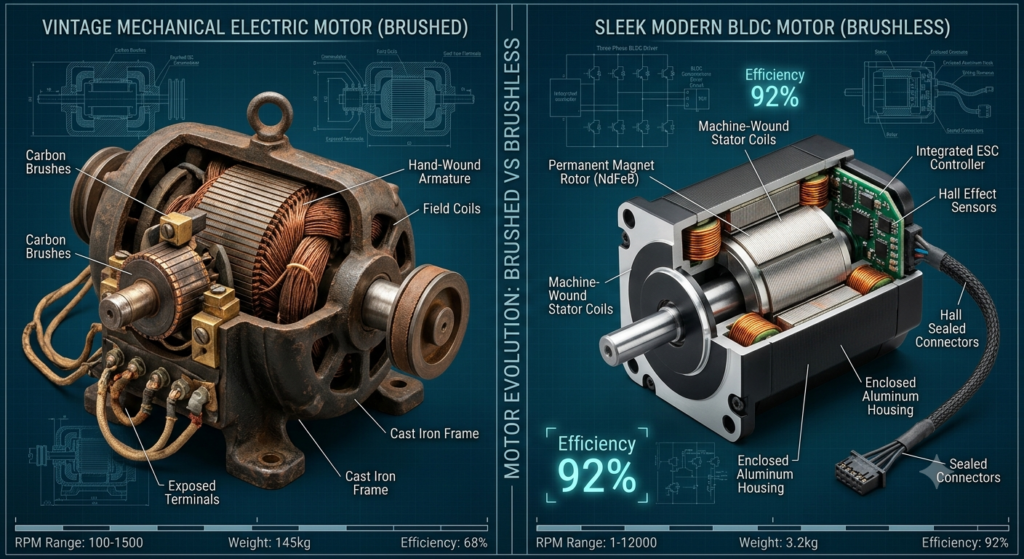
Purani brushed motor mein, carbon brushes physically ghoomne wale commutator ko touch karte the taaki current ki direction badli ja sake. Is ghissao (friction) ki wajah se carbon dust jamti thi aur motor ki life sirf 2,000 se 3,000 ghante hi rehti thi.
Brushes aur mechanical commutator ko hatane ke liye switching ko mechanical se solid-state electronic switching par shift karna zaroori tha.
⏳Evolution & Historical Milestones
1. Solid-State Transistors ka AanaLate 1950s
Jab semiconductor transistors market mein aaye, tab bina kisi physical contact ke high-speed electronic switching karna possible hua.
2. Pehla BLDC Concept1962
T.G. Wilson aur P.H. Trickey ne apne landmark research paper “D.C. Machine With Solid-State Commutation” mein duniya ko dikhaya ki kaise solid-state circuits se traditional brushes ko replace kiya ja sakta hai.
3. Hall Effect Sensors ka Integration1970s
Researchers ne stator ke andar Hall-effect magnetic sensors lagaye, jisse rotor ki exact position detect karke perfect electronic switching acheive ki gayi.
4. Permanent Magnets ki Kranti1980s (1984)
1984 mein Neodymium-Iron-Boron (NdFeB) magnets ka aavishkar hua. Older Ferrite magnets ko NdFeB se replace karne par motor ka size chota ho gaya aur overall efficiency 90%+ tak chali gayi.
Mechanical se Electronic Commutation par kyun shift huye?
Traditional motors ko chhadd kar BLDC technology par aane ke picche main reasons the:
⚡Key Advantages & Performance Benefits
1. Behtar Heat ManagementThermal Efficiency
BLDC mein copper windings bahar wale static frame (stator) par hoti hain, jisse heat direct bahar Dissipate ho jaati hai aur temperature control mein rehta hai.
2. Aawaz aur Sparks Se ChutkaraSilent Operation
Mechanical contact bilkul khatam hone se electrical sparking aur frictional shor (noise) puri tarah band ho jata hai.
3. Precise Speed ControlDigital Precision
Microprocessor aur Electronic Speed Controller (ESC) ki madad se motor ki speed ko bohot hi accurate tarike se control aur tune kiya ja sakta hai.
Historical transition from mechanical commutators to modern solid-state BLDC designs.
Working Principle: Magnetic Stator, Permanent Magnet Rotor, and Sensors
Ek standard Brushless DC (BLDC) motor traditional Brushed DC motor ka ulta (inside-out) architecture follow karti hai.
⚙️Anatomy & Structural Components
Stator (Stationary Part)Copper Windings
Isme high-permeability steel laminations par copper coils ki winding hoti hai. Isko 3-Phase configuration (U, V, W) mein connect kiya jata hai taaki electromagnetic field generate ho sake.
Rotor (Rotating Part)Permanent Magnets
Isme high-grade permanent magnets (jaise Neodymium NdFeB) lage hote hain, jo bina kisi physical contact ya friction ke magnetic interaction ke zariye ghoomte hain.
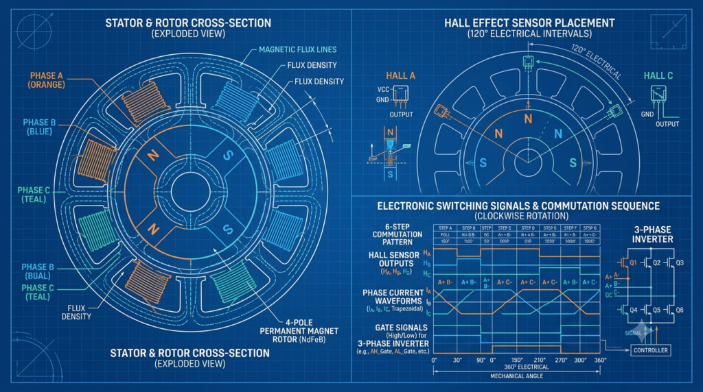
Electronic Commutation sequence mein microcontroller Inverter MOSFETs ke jariye 3-phase windings ko sequential order mein energize karta hai. Stator mein banna wala rotating magnetic field (RMF) rotor ke permanent magnets ko aage khinchta (attract/repel) hai, jisse rotation milta hai.
Internal structural layout of a 3-phase BLDC Motor highlighting the position of Hall sensors relative to stator windings.
Hall Effect Sensors vs. Sensorless BLDC Control
BLDC Motor mein electronic switches (MOSFETs) ko sahi waqt par turn-on/off karne ke liye Microcontroller ko rotor ki exact position pata honi chahiye. Position detect karne ke do tarike hain:
🔄 SENSORED VS. SENSORLESS BLDC COMPARISON
Parameter
Sensored BLDC (Hall Sensors)
Sensorless BLDC (Back-EMF Sensing)
Position Sensing Device
3 Digital/Analog Hall Sensors (spaced at 60° or 120°)
No physical sensors; measures Back-EMF voltage on unenergized winding
Low/Zero-Speed Torque
Excellent; full torque available at 0 RPM
Poor at startup; requires open-loop acceleration to generate Back-EMF
Wiring & Connections
Requires 8 wires (3 Phase power wires + 5 Hall sensor wires)
Only 3 Phase power wires needed
Cost & Reliability
Higher cost; sensors can fail at high temperatures (>150°C)
Lower cost; high reliability in harsh environments
Common Applications
Electric Vehicles (EVs), E-bikes, Robotics, Heavy Load Starters
Ceiling Fans, Pumps, Compressors, Drones
Core Engineering Formulas (Torque, Back-EMF, and Efficiency)
Ek Motor Engineer ke point of view se BLDC performance ko mathematically analyze karne ke liye neeche diye gaye key formulas use kiye jaate hain:
⚡ 1. Back-Electromotive Force (Back-EMF)
Jab permanent magnet rotor stator coils ke saamne ghoomta hai, toh Faraday’s Law of Electromagnetic Induction ke tahat coils mein voltage induce hota hai jise Back-EMF (e) kehte hain:
Back-EMF Equation
e = Ke · ωm
Where:
e= Back-EMF Voltage (V)
Ke= Back-EMF Constant (V·s/rad)
ωm= Mechanical Angular Velocity (rad/s)
💡 Engineering Insight: Back-EMF directly motor speed (ωm) ke proportional hota hai. High RPM par Back-EMF DC bus voltage ke barabar ho jata hai, jo motor ki maximum speed limit decide karta hai.
⚙️ 2. Electromagnetic Torque Equation
BLDC motor dwara produce kiya gaya electromagnetic torque (Te) motor ke torque constant (Kt) aur phase current (Ia) ke directly proportional hota hai:
Electromagnetic Torque Equation
Te = Kt · Ia
📐 Ideal SI Units Equality: Standard SI units mein, torque constant aur Back-EMF constant numerical value mein ek saman hote hain:
Kt (N·m/A) = Ke (V·s/rad)
📈 3. Terminal Voltage & Speed-Torque Relationship
Steady-state condition mein jab inductance loss negligent ho (Ls · dIa/dt ≈ 0), tab single-phase terminal voltage aur mechanical velocity (ωm) ka relationship nikalta hai:
Speed-Torque Velocity Equation
ωm = V − Ia · RsKe
Parameter Nomenclature:
V= Applied DC Bus Voltage (V)
Rs= Stator Winding Resistance (Ω)
Ls= Stator Phase Inductance (H)
🎯 4. Motor Efficiency (η)
Efficiency Electrical Input Power (Pin) aur Mechanical Output Power (Pout) ke ratio ko percentage mein darshati hai:
🔧 Workshop Mechanic Tip: Jab ek BLDC fan ya motor repair ke liye workshop mein aati hai, toh mechanic ko sirf theory nahi, balki components ki physical testing ki zarurat hoti hai.
✅ Result Standard: Teeno values lagbhag identical honi chahiye (Variation < 1%). Agar ek phase ka resistance baaki se kafi kam hai, toh short-circuit (burnt insulation) ki problem hai.
2. Hall Sensor Diagnostics
Hall Sensor board par 5V DC supply dein.
Multimeter ko Voltage Mode par rakhein aur Signal output wire aur Ground ke beech voltage check karte waqt rotor ko haath se slow rotate karein.
✅ Result Standard: Voltage 0V se 5V ke beech continuously toggle hona chahiye. Agar voltage 0V ya 5V par stuck rahe, toh sensor damaged hai.
3. MOSFET Inverter Check
Controller PCB par lage Inverter MOSFETs ke Drain aur Source terminal ke beech Diode Test Mode mein testing karein.
✅ Result Standard: Normal forward voltage drop 0.4V – 0.7V ke beech hona chahiye. Short circuit ya 0V aane par MOSFET blown (damaged) hota hai.
Chapter 3: Comparative Analysis- BLDC Motor vs. Induction (AC) vs. Brushed DC
Electrical motor selection mein koi bhi single motor “universal answer” nahi hoti. Har motor technology ke apne performance trade-offs, thermal properties, aur maintenance demand hoti hain. Sub-fractional horsepower applications (jaise ceiling fans, drones, HVAC, aur EVs) mein BLDC ne traditional motors ko replace kar diya hai.
Direct Parameter Comparison (Efficiency, Noise, Heat, Maintenance, Life Span)
Neeche diye gaye parameters ek Engineer ke performance requirements aur Workshop Mechanic ke long-term reliability observations par based hain:
📊 BRUSHED DC VS. AC INDUCTION VS. BLDC MOTOR
Parameter
Brushed DC Motor
AC Induction (Single-Phase)
BLDC Motor (Brushless DC)
Efficiency (η)
Moderate (60% − 75%)
Low to Moderate (55% − 70%)
High (85% − 95%+)
Commutation Method
Mechanical (Carbon Brushes + Commutator)
Self-Commutated via Rotating AC Magnetic Field
Electronic (MOSFET Inverter driven by MCU)
Heat Generation Location
Armature (Rotor) — Heat trap hota hai
Stator & Rotor (Eddy currents in rotor bars)
Stator only — Frame se direct heat dissipate ho jati hai
Speed-Torque Characteristic
Flat across range; torque drops at high speeds
Non-linear; limited by AC grid frequency (50Hz/60Hz)
Flat across wide speed range; high torque at startup
Acoustic & Electrical Noise
High (Mechanical friction + Carbon arcing EMI)
Moderate (AC 50Hz hum + mechanical resonance)
Extremely Low (No mechanical contact; High PWM Frequency >20kHz)
Maintenance & Service Life
High Maintenance (Brush change every 1,500−3,000 hrs)
Low Maintenance (Bearing wear only; >15,000 hrs)
Zero Motor Maintenance (Bearing limited; >30,000 hrs)
Power Factor (cosφ)
Near Unity (1.0)
Low (0.6−0.85), requires run capacitor
High (0.90−0.98) with Active PFC in Driver
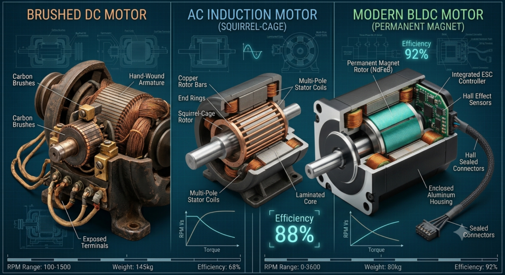
Cross-sectional architectural comparison highlighting commutator assembly in Brushed DC, squirrel cage in AC Induction, and permanent magnets in BLDC.
Technical Trade-offs & Cost Analysis (Engineer vs. Workshop Mechanic View)
⚖️ ENGINEERING VS WORKSHOP PERSPECTIVE
📐 ENGINEER’S FOCUS
High Energy Efficiency (>90%): Direct carbon footprint kam karta hai.
Current external DC source se physical carbon brushes ke jariye rotating commutator bar par jaata hai. Constant friction se carbon dust banta hai jo internal insulation ko degrade karta hai.
2AC Induction Motor
Stator 3-Phase AC supply se rotating magnetic field banta hai jo rotor ke squirrel cage bars mein voltage induce karta hai (Vrotor ∝ slip). Magnetic field lagging hoti hai, jise Slip Speed kehte hain:
Slip Ratio Equation
s = Ns − NrNs
(Jahan Ns = Synchronous Speed, Nr = Rotor Speed)
3BLDC Motor (Zero Slip)
BLDC mein Zero Slip hota hai. Rotor permanent magnets (NdFeB) ke synchronous pull ki wajah se stator magnetic field ke saath exact speed par lock hokar ghoomta hai:
Synchronous Speed Equation
Ns = 120 · fP
(Jahan f = Inverter Switching Frequency in Hz, P = Number of Poles)
Energy transition sirf ek engineering trend nahi hai—ye ek zaroori economic shift hai. Electricity consumption ka ek bada hissa rotary motion (motors aur fans) mein jata hai. Single-phase induction fans ko BLDC technology se replace karne se individual household budgets se lekar global rare-earth mineral demand tak sab kuch affect hota hai.
Personal Savings: Electricity Bills & Payback Period Calculation
💡Energy Efficiency & Power Savings
Ghar ke level par, BLDC ceiling fan ka sabse bada attraction uski energy efficiency hai. Same CFM (Cubic Feet per Minute) air delivery dene ke bawajood BLDC technology Bijli ki khapat (power consumption) ko aadhi se bhi kam kar deti hai.
Standard Fan Price = ₹1,800 | BLDC Fan Price = ₹3,500 (Diff: ₹1,700)
Per Year Savings = ₹2,196 / year
$$T_{\text{payback}} = \frac{₹1,700}{₹2,196} \approx \mathbf{0.77 \text{ Years (9.2 Months)}}$$
Financial Conclusion: 10 mahine se bhi kam samay mein BLDC fan ka extra price electricity bill savings se completely zero ho jata hai. Iske baad, agle 8–10 saalon tak yeh device pure positive return/savings deta hai.
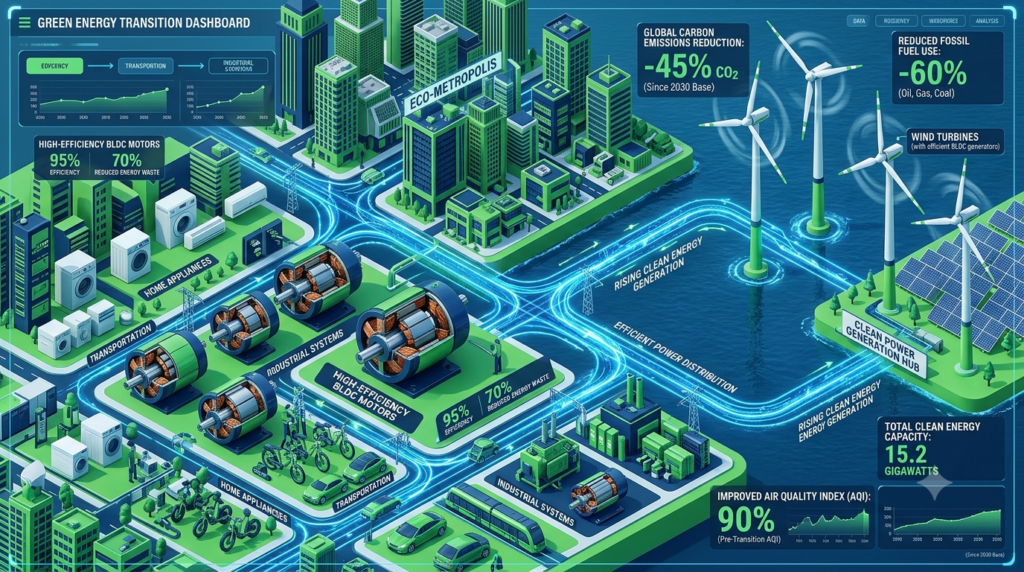
Macro-level energy reduction impact when shifting millions of residential induction motors to BLDC technology.
National Impact: Grid Load Reduction, Carbon Footprint & Energy Policies
Total National Energy Grid Savings⚡ SAVINGS: 23.5 Gigawatts Peak Power Saved
🌱 MACRO-ECONOMIC & ENVIRONMENTAL IMPACT
1Peak Load Reduction
23.5 GW electricity save hona 10–12 bade Thermal Power Generation Plants (2000 MW capacity each) ke installation aur operational cost ko save kar sakta hai.
2Carbon Footprint Reduction
India mein 1 kWh electricity generate karne se lagbhag 0.82 kg CO2 produce hota hai (coal-dominant power mix). Har BLDC fan saal mein ~274.5 kWh electricity bachat karta hai.
CO₂ Emission Saved per Fan / Year
274.5 kWh × 0.82 kg CO2/kWh = 225 kg CO2 / Year
🌎National Scale Impact: Agar 10 crore fans ko bhi BLDC mein convert kar diya jaye, toh 2,250,000 Metric Tonnes CO2 ka annual emission kam hoga.
3Government Initiatives (BEE Star Labeling)
Bureau of Energy Efficiency (BEE) ne ceiling fans ke liye Star Labeling mandatory kar di hai. 5-Star Rating pane ke liye fans ko BLDC ya ultra-efficient motor architecture use karna hi padta hai.
Global Transition: Renewable Energy Integration & Economic Downside
BLDC technology ke jahannam aur jannat dono aspect hain. Global transition mein benefits ke sath-sath strategic vulnerabilities bhi hain:
1. Renewable Energy & Off-Grid Optimization (Solar & Battery)
☀️Solar & Battery Integration
BLDC motors natively DC Powered hoti hain (unka driver internal AC-to-DC conversion karta hai). Direct DC Solar PV Systems aur Battery Storage (Rooftop Solar) ke sath inka conversion loss minimum hota hai.
AC FAN
Normal AC Fan run karne ke liye Solar Inverter (DC to AC) chalana padta hai, jis se ~15% Inverter Conversion Loss waste hota hai.
BLDC FAN
BLDC Fan directly 12V / 24V / 48V DC Bus par chal sakta hai — jis se overall solar system efficiency +25% tak badh jaati hai.
Net Off-Grid Solar System Efficiency Boost:+25% Savings
2. The Economic Downside & Supply Chain Vulnerability: Rare Earth Elements
🧲 Rare-Earth Permanent Magnet Component
BLDC motor ka substantial efficiency gain Neodymium-Iron-Boron
Nd2Fe14B
permanent magnets par dependent hota hai.
Chemical Compound Formula:
$$\text{Nd}_2\text{Fe}_{14}\text{B}$$
⚠️ RARE EARTH DEPENDENCY & CRITICAL RISK
🌍 Global Supply Dominance:
China controls ~70% of NdFeB mining and >85% of global refining capacity.
📈 Price Volatility:
Neodymium and Dysprosium raw material prices fluctuate drastically in international markets.
☣️ Environmental Hazard:
Rare earth mining and chemical extraction produce heavy toxic waste and radioactive tailings.
🚨 Geopolitical Risk:
Trade restrictions and supply embargoes directly disrupt global EV and BLDC motor manufacturing.
Engineering Mitigation Trend:
Engineers ab Ferrite Magnet BLDC designs aur Synchronous Reluctance Motors (SynRM) devlop kar rahe hain taaki Rare Earth NdFeB magnets par dependency kam ho sake, halanki Ferrite designs mein motor size thoda bada ho jata hai.
Chapter 5: Market Landscape: Top Manufacturers & Buyers’ Guide
BLDC motors aur fans ka market bohot fast grow kar raha hai. Consumer ceiling fans se lekar industrial drives aur EVs tak, market mein traditional manufacturers aur tech-focused startups dono shamil hain.
Global & Indian BLDC Motor/Fan Brands
1. Appliance & Fan Segment (Consumer Goods)
🏭Indian Market Key Players
Atomberg TechnologiesPioneer Brand
India mein BLDC fans ke adoption ka pioneer brand. Smart features, micro-controllers (AtomSENSE algorithm), aur ultra-low wattage (28W) power efficiency par primary focus.
Crompton & HavellsLegacy Giants
Traditional electrical giants jo ultra-efficient motor designs (jaise Energion series) aur apne massive offline distribution network ke sath market share lead kar rahe hain.
2. Industrial & Automotive BLDC Motor Manufacturers
🌐Global & Industrial Manufacturers
Maxon Group & Nidec CorporationGlobal Leaders
Precision robotics, drones, medical devices, aur high-performance automotive BLDC motors ke global market leaders.
Bharat Bijlee, Rotomag & MechtexIndustrial & EV Specialists
India-based heavy industrial manufacturers jo solar pumping, industrial automation, aur EV propulsion systems ke liye high-torque BLDC motors develop karte hain.
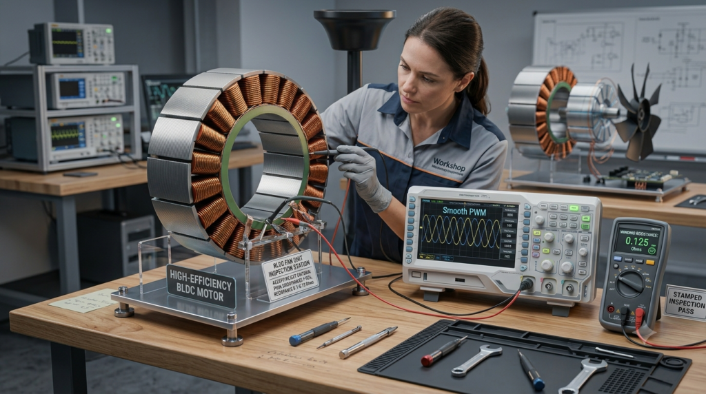
Technical testing setup for evaluating BLDC motor winding balance, driver MOSFET signals, and controller quality.
Buyer’s Checklist: What to Look for Before Purchasing
Khareedte waqt sirf brand name ya outer design nahi, balki internal technical specifications par dhyan dena zaroori hai:
📋 BLDC BUYER’S EVALUATION MATRIX
Parameter
Recommended Standard
1. Copper Winding
100% Pure Electrolytic Copper (Avoid Aluminium)
2. Bearing Quality
Double Precision Ball Bearings (e.g., SKF, NBC)
3. Air Delivery (CMM)
≥ 220 to 230 CMM(Cubic Meters per Minute)
4. Power Factor (PF)
≥ 0.95(Active Power Factor Correction – PFC)
5. Operating Voltage
90V – 300V AC(With internal surge protection)
6. Warranty
Minimum 2 to 3 Years (Covering PCB + Motor)
Workshop Reality Check: Common Failure Points & Repairability
🔧 Workshop Mechanic Insight: “BLDC motor kabhi nahi jalti, driver board pehle urta hai!”
Workshop analysis ke mutabiq, 85% BLDC fan failures Electronic Speed Controller (ESC) mein hote hain, motor physical assembly mein nahi.
🔧 COMMON FAILURE CAUSES & DIAGNOSTIC TABLE
Failure Symptom
Root Cause
Repair Action
❌ Fan completely dead (No LED response)
Input Surge / Fuse Varistor (MOV) blown due to high voltage spike.
Replace MOV / Input Fuse on Driver PCB
⚠️ Fan jerks or hums (Won’t rotate smoothly)
Single-phase MOSFET failure or open-circuit in stator winding.
Replace blown SMD MOSFETs / Re-solder phase wires
📡 Remote control not responding
Receiver IR sensor failure or un-paired RF remote module.
Re-pair remote or Replace IR/RF sensor board
🔊 Mechanical grinding sound
Bearing wear-and-tear or Shaft misalignment.
Replace damaged bearings (SKF 608/6202)
Mechanic’s Advice for Longevity:
🛡️PCB Safety & Durability
1Surge Protection
Voltage Spikes
Sahi Inverter-compatible BLDC fans khareedein jinke PCB mein Metal Oxide Varistor (MOV) aur High Transient Voltage Suppressor (TVS) diodes integrated hon, jo high voltage fluctuations aur surges se driver unit ko protect karte hain.
2Thermal Dissipation
Heat Management
Fan ke canopy ya outer casing mein proper venting holes hone chahiye taaki internal driver PCB par excessive heat accumulate na ho aur circuit elements long-term reliability ke sath operate kar sakein.
Chapter 6: Standard References & Technical Bibliography
📚Academic & Industrial References
[1]
IEEE Standard 1415-2006:IEEE Guide for Induction Machinery Maintenance Applications.
[2]
Wilson, T. G., & Trickey, P. H. (1962):“D.C. Machine With Solid-State Commutation.” IEEE Transactions on Applications and Industry, 81(5), 256–263.
[3]
Hanselman, D. C. (2006):Brushless Permanent Magnet Motor Design. McGraw-Hill, Inc.
[4]
Bureau of Energy Efficiency (BEE), Ministry of Power, Govt. of India:Standards & Labeling Scheme for Electric Ceiling Fans.
[5]
Krause, P. C., Wasynczuk, O., & Sudhoff, S. D. (2013):Analysis of Electric Machinery and Drive Systems. Wiley-IEEE Press.
Is blog post mein di gayi sabhi technical information, engineering formulas, historical data, aur market metrics authentic research papers, IEEE journals, aur manufacturer technical datasheets se verify kiye gaye hain.
⚠️ Safety Note: Kisi bhi practical installation, component replacement, ya workshop repair ke dauran aane wale kisi bhi damage, electrical accident, ya financial loss ke liye lekhak (author) ya website owner zimmedar nahi honge. Physical work hamesha trained certified electricians ya proper safety gear ke sath hi karein.
Note: Is article mein istemaal ki gayi sabhi visual images AI-generated (Artificial Intelligence) hain. Realistic depiction ke bawajood, actual physical components aur branding images asli product se thodi alag ho sakti hain.