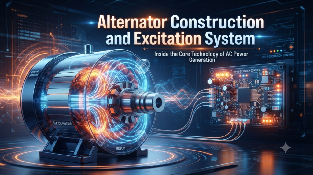
Alternator की Construction, Types, Excitation और AVR
Introduction
पिछले भाग में हमने Alternator के basic concept को समझा था।
Part 1 — AC Generator: कैसे बनती है Electricity? Alternator की पूरी कहानी
अब हम उस knowledge को आगे बढ़ाते हुए Alternator को अंदर से बाहर तक समझेंगे।
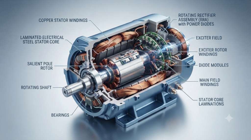
जब हम किसी बड़े Alternator को बाहर से देखते हैं तो यह एक भारी industrial machine दिखाई देता है। लेकिन इसके अंदर कई अलग-अलग systems एक साथ काम करते हैं।
एक typical synchronous Alternator में मुख्य रूप से निम्न components होते हैं:
इनमें से प्रत्येक component का अपना specific engineering function है।
1 — Alternator की Construction को समझने का सही तरीका
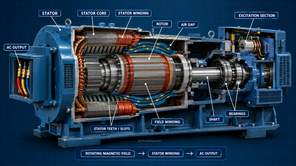
Alternator की construction को समझने के लिए सबसे आसान तरीका है इसे तीन मुख्य हिस्सों में देखना:
यह Stator side है।
यह Rotor और Shaft side है।
यह Rotor में magnetic field को establish और control करने में सहायता करता है।
Prime Mover ➔ Shaft ➔ Rotor ➔ Rotating Magnetic Field ➔ Air Gap ➔ Stator Winding ➔ AC Output
Voltage Sensing ➔ AVR ➔ Excitation System ➔ Rotor Field
2 — Stator क्या होता है?
Alternator का stationary (स्थिर) हिस्सा Stator कहलाता है। Stator machine के fixed structure में mounted होता है।
Stator मुख्य रूप से 5 बड़े पार्ट्स से मिलकर बना होता है:
Stator rotate नहीं करता। जब Rotor घूमता है, तो उसका magnetic field stator winding के सापेक्ष (relative) continuously बदलता रहता है। इस changing magnetic linkage के कारण stator winding में EMF (Voltage) induce होती है।
इसीलिए conventional synchronous Alternator का main electrical output हमेशा Stator Winding से ही लिया जाता है।
3 — Stator Frame
Stator Frame, Alternator का stationary mechanical structure होता है। यह मशीन का बाहरी ढाँचा (housing) है जो अंदरूनी सभी इलेक्ट्रिकल और मैग्नेटिक कॉम्पोनेंट्स को सुरक्षित रखता है।
Stator Frame के मुख्य कार्य (Key Functions) निम्नलिखित हैं:
4 — Stator Core और Laminations
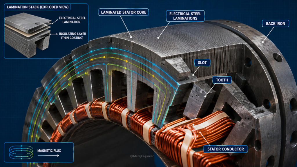
Stator core, Alternator के magnetic circuit का बहुत महत्वपूर्ण हिस्सा है। इसे सामान्यतः thin electrical-steel laminations से बनाया जाता है।
सवाल: Laminations क्यों इस्तेमाल की जाती हैं?
Alternating magnetic flux के कारण conducting core के अंदर स्वाभाविक रूप से eddy currents पैदा होने लगते हैं। ये currents:
का कारण बनते हैं। Thin insulated laminations इन eddy-current circulation को कम करने में सहायता करती हैं।
Laminated Core ➔ Lower Eddy-Current Loss ➔ Better Thermal / Efficiency Performance
5 — Stator Slots और Teeth
Stator core की inner circumference (अंदरूनी परिधि) पर बने openings Slots कहलाते हैं। इन slots में stator winding के conductors या coil sides रखे जाते हैं।
Inner circumference पर बने कटआउट्स, जिनमें winding conductors रखे जाते हैं।
दो adjacent slots के बीच का iron portion, जो flux carry करता है और winding को support देता है।
Slots + Teeth + Back Iron
6 — Stator Conductors और Coils
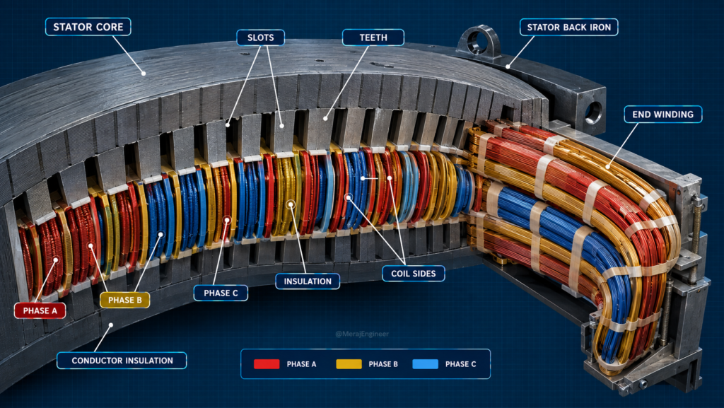
Stator core के slots में उच्च गुणवत्ता के Copper Conductors रखे जाते हैं। इन conductors को निर्धारित turns और विशेष geometry के अनुसार अरेंज करके coils बनाई जाती हैं।
Winding Construction Process:
Copper Conductors ➔ Specific Turns/Coils ➔ Electrical & Spatial Interconnection ➔ Stator Winding
कई coils को सटीक electrical और spatial arrangement के अनुसार आपस में जोडकर Stator Winding का निर्माण किया जाता है।
7 — Three-Phase Stator Winding
Industrial Alternators में Three-Phase Winding सबसे आम और मानक (standard) तरीका है।
इसमें मुख्य रूप से तीन अलग-अलग Phase Groups होते हैं:
इन windings को stator slots में spatially distributed (विशेष स्थान दूरी के हिसाब से) रखा जाता है।
120° Electrical Displacement
8 — Coil Pitch, Full-Pitch और Short-Pitch Winding
Winding design में Coil Pitch एक अत्यंत महत्वपूर्ण parameter है जो generated voltage की waveform और quality को तय करता है।
जब coil span लगभग एक full pole pitch (180° electrical) के बराबर होता है।
जब coil span को full pole pitch से थोड़ा छोटा (< 180° electrical) रखा जाता है।
Short-pitching का उपयोग करने के मुख्य उद्देश्य:
9 — Distributed Winding और End Winding
यदि Phase Winding को एकाधिक (multiple) slots में फैलाकर बिछाया जाता है, तो इसे Distributed Winding कहा जाता है।
यह generated EMF waveform को sinusoidal और बेहतर बनाने तथा unwanted harmonics को कम करने में सहायता करती है।
Stator slots से बाहर की तरफ निकलने वाला और मुड़ने वाला winding portion End Winding कहलाता है।
10 — Rotor क्या होता है?
Alternator का घूमने वाला (rotating) घटक Rotor कहलाता है। Rotor सीधे Shaft के साथ जुड़ा होता है और उसी के साथ rotate करता है।
Magnetic Field Establish करना
जब Rotor घूमता है, तो इसके द्वारा बनाया गया Magnetic Field भी Stator के सापेक्ष (relative) लगातार घूमता है।
11 — Rotor के दो प्रमुख Construction Types
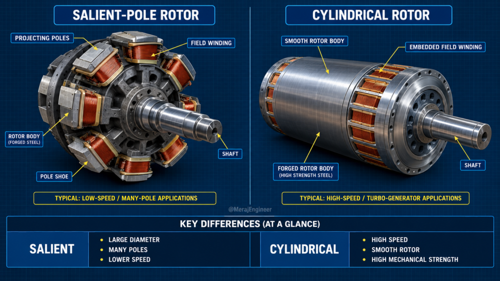
Synchronous Alternator में Rotor Construction के दो प्रमुख Forms होते हैं:
Projecting (बाहर निकले हुए) poles वाला rotor design।
Smooth cylindrical surface (Non-salient) वाला rotor design।
12 — Salient-Pole Rotor
Salient शब्द का अर्थ होता है — Projecting (बाहर की ओर निकले हुए)। Salient-pole rotor में अलग-अलग magnetic poles rotor body की मुख्य सतह से बाहर की तरफ निकले होते हैं, जिन पर field winding लपेटी जाती है।
Salient-Pole Rotor की मुख्य विशेषताएँ (Typical Characteristics):
[Hydroelectric generators में salient-pole construction](https://www.energy.gov/cmei/water/how-hydropower-works) अत्यधिक उपयोग किया जाता है।
13 — Cylindrical Rotor
Cylindrical rotor को non-salient या smooth rotor भी कहा जाता है। इसमें बाहर की ओर निकले हुए (projecting) poles नहीं होते। इसकी Field winding rotor body में काटे गए slots में embedded होती है।
Cylindrical Rotor की मुख्य विशेषताएँ (Typical Characteristics):
14 — Rotor Field Winding
Wound-field synchronous Alternator में Rotor Field Winding को DC Excitation (Direct Current) दी जाती है। यह DC Current Rotor के अंदर स्थिर polarity वाला magnetic field establish करता है।
Electromagnetic Sequence Flow:
DC Field Current ➔ Rotor Magnetic Field ➔ Rotating Magnetic Field
जब Rotor Shaft घूमता है, तो Rotor के साथ उसका magnetic field भी घूमने लगता है।
15 — Shaft और Bearings
Shaft वह मुख्य मैकेनिकल घटक है जो Prime Mover (जैसे Engine या Turbine) से आने वाले Torque को Rotor तक ट्रांसफर करता है।
Mechanical Torque Path:
Prime Mover ➔ Shaft ➔ Rotor
Bearings rotor shaft को दोनों सिरों पर मजबूत mechanical support प्रदान करते हैं और कम से कम घर्षण (friction) के साथ smooth rotation सुनिश्चित करते हैं।
Bearing Failures / Problems के दुष्परिणाम:
16 — Air Gap
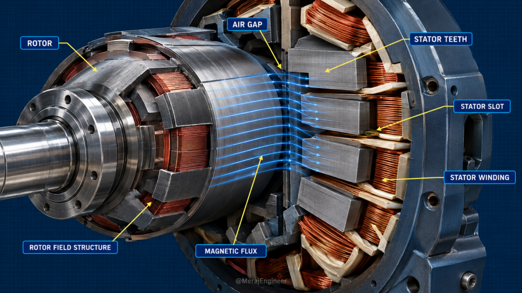
Alternator के अंदर Rotor और Stator आपस में भौतिक (physical) रूप से स्पर्श नहीं करते। दोनों के बीच एक नियंत्रित दूरी यानी Air Gap रखा जाता है।
Air Gap की दोहरी भूमिका (Dual Role):
Air-gap का सटीक आकार (dimension) मशीन डिज़ाइन, excitation requirements, mechanical tolerances और समग्र electromagnetic performance को सीधे प्रभावित करता है।
17 — Excitation System क्या है?
Rotor field को magnetic field establish करने के लिए Direct Current (DC) सप्लाई की आवश्यकता होती है। इस DC current को प्रदान करने और नियंत्रित करने की पूरी व्यवस्था को ही Excitation System कहा जाता है।
Excitation System के 3 मुख्य कार्य (Broad Functions):
Excitation Source ➔ Rotor Field ➔ Magnetic Field
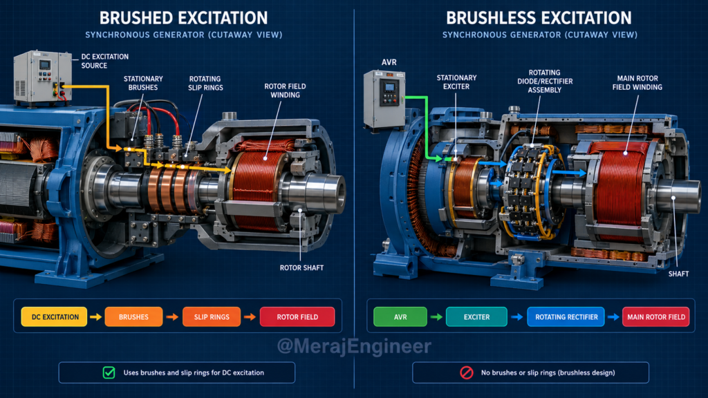
18 — Brushed Excitation
Brushed Excitation System में Rotor Field Winding तक DC current पहुँचाने के लिए Brushes और Slip Rings के मैकेनिकल कॉम्बिनेशन का उपयोग किया जाता है।
Basic Power Transfer Path:
DC Excitation Source ➔ Brushes ➔ Slip Rings ➔ Rotor Field
यह मशीन के Stationary (स्थिर) हिस्से पर माउंट होती हैं और बाहरी DC सप्लाई से जुड़ी रहती हैं।
यह Rotor Shaft पर लगी होती हैं और Shaft के साथ ही लगातार rotate करती हैं।
19 — Brushless Excitation
Brushless Excitation Architecture में Main Rotor Field तक DC current पहुँचाने के लिए किसी भी तरह की पारंपरिक Brushes और Slip Rings की आवश्यकता नहीं होती।
Typical Power & Control Path:
AVR ➔ Exciter ➔ Rotating Rectifier ➔ Main Rotor Field
यह व्यवस्था आधुनिक और बड़े Industrial Synchronous Generators में अत्यधिक लोकप्रिय और मानक (standard) तरीका है।
20 — Exciter क्या करता है?
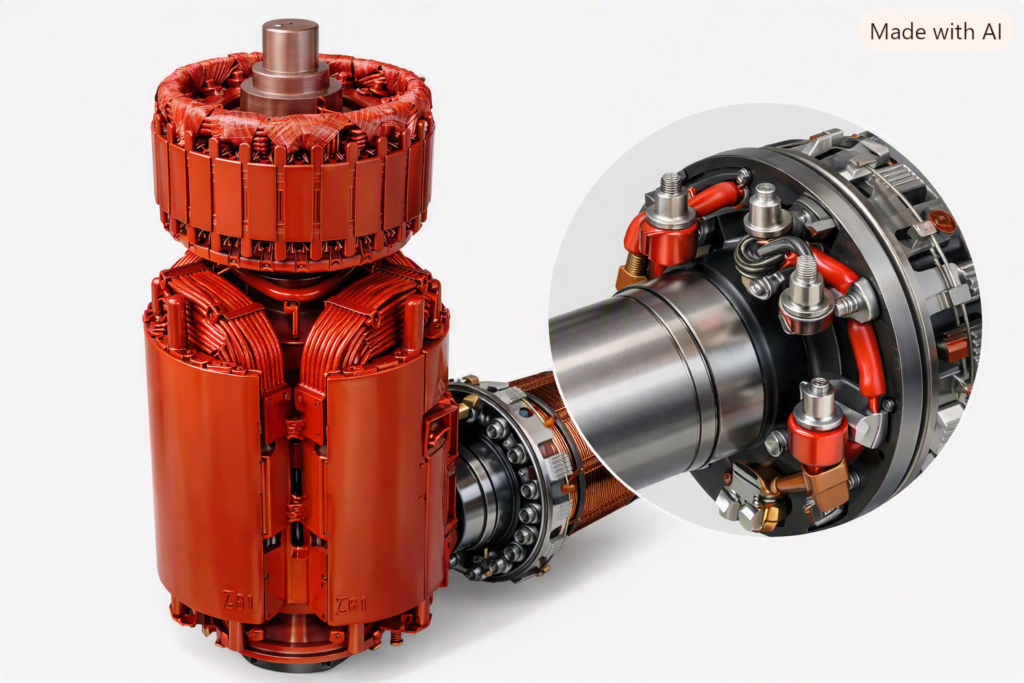
Exciter एक auxiliary (सहायक) electrical machine या system होता है जो मुख्य Alternator के Rotor Field के लिए आवश्यक excitation power जनरेट करता है।
Brushless Architecture में Power Conversion Path:
Exciter AC Output ➔ Rotating Rectifier ➔ Rectified DC ➔ Main Rotor Field
Brushless system में Exciter से निकलने वाला AC output सीधे Rotating Rectifier Assembly तक भेजा जाता है, जो शाफ्ट के साथ घूमते हुए AC को DC में बदल देती है।
21 — Rotating Rectifier Assembly (RRA) और Diodes
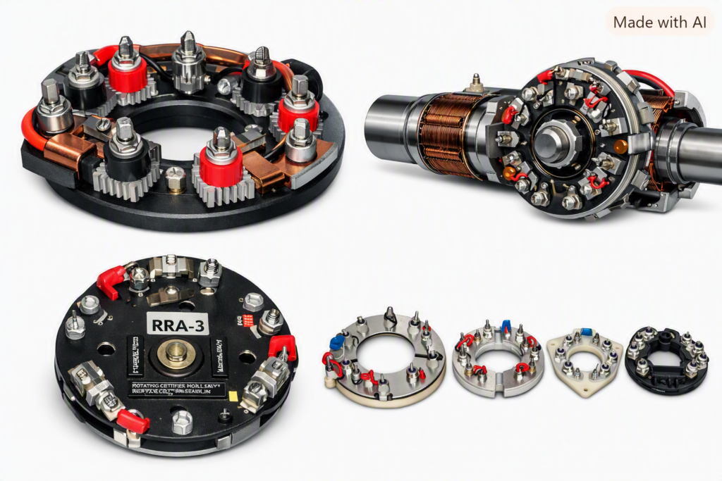
Brushless Excitation System में Main Rotor Field Winding तक DC Excitation पहुँचाने के लिए Rotating Rectifier Assembly (RRA) का उपयोग किया जाता है। यह Assembly सीधे Rotor Shaft के साथ घूमती है और Exciter से प्राप्त AC Electrical Output को Rectified DC में Convert करती है।
Power Rectification Flow:
Exciter AC Output ➔ Rotating Rectifier ➔ DC Field Current ➔ Main Rotor Field Winding
RRA में Diodes का उपयोग: Three-phase brushless excitation systems में Multiple Power Diodes को Three-Phase Full-Wave Rectifier के रूप में Arrange किया जाता है।
1N5408 एक General-Purpose Silicon Rectifier Diode है, जिसकी Forward-Current Rating लगभग 3 A होती है। Large Industrial Alternators में Excitation Requirements के अनुसार Stud Type या Press-Fit Power Diodes (जैसे 25A, 35A, 70A, 100A) उपयोग किए जाते हैं।
Diode Part Number ≠ Alternator Type
22 — AVR क्या होता है?
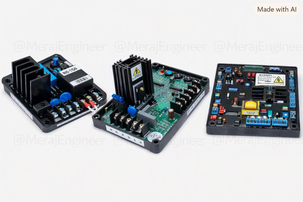
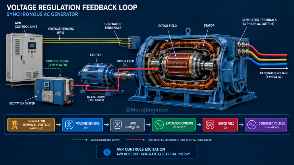
AVR का पूरा नाम Automatic Voltage Regulator है। यह अल्टरनेटर का मुख्य इलेक्ट्रॉनिक कंट्रोल सिस्टम है जो जनरेटर की आउटपुट वोल्टेज को स्थिर (constant) बनाए रखने का काम करता है।
Simplified Closed-Loop Control System:
Terminal Voltage ➔ Voltage Sensing ➔ AVR ➔ Excitation Control ➔ Rotor Field ➔ Generator Voltage
23 — Alternator के Types को सही तरीके से समझें
Alternator कितने प्रकार के होते हैं?
इसका कोई एक निश्चित उत्तर (single fixed number) देना तकनीकी रूप से सही नहीं है, क्योंकि Alternators को कई अलग-अलग मानदंडों (parameters) के आधार पर वर्गीकृत किया जाता है।
उदाहरण के लिए, एक ही अल्टरनेटर एक साथ ये सभी हो सकता है:
Three-Phase + Synchronous + Salient-Pole + Hydro + Brushless + AVR-Controlled + Air-Cooled
24 — Phase और Rotor के आधार पर Classification
- Single-Phase: छोटे जनरेटर्स या घरेलू उद्देश्यों के लिए।
- Three-Phase: Industrial power generation में सर्वाधिक इस्तेमाल होने वाला मानक रूप।
- Salient-Pole: Projecting poles, low speed operations के लिए।
- Cylindrical: Smooth outer surface, high speed turbo-generators के लिए।
25 — Application के आधार पर Alternator
Application और Prime Mover के आधार पर प्रैक्टिकल फ़ील्ड में अल्टरनेटर के कई प्रचलित नाम सुनने को मिलते हैं:
ध्यान दें कि ये सभी नाम एक ही टेक्निकल क्लासिफिकेशन का हिस्सा नहीं हैं, बल्कि ये अलग-अलग सिस्टम्स और पैरामीटर्स का कॉम्बिनेशन हैं:
- Hydro ➔ Prime-mover / Application context
- Salient-Pole ➔ Rotor construction type
- Brushless ➔ Excitation architecture
- AVR ➔ Voltage control system
- Air-Cooled ➔ Cooling method
26 — Hydro Generator
Hydro Generator में पानी की ऊर्जा से चलने वाली Water Turbine द्वारा अल्टरनेटर को Mechanical Energy प्राप्त होती है।
Water Energy ➔ Hydraulic Turbine ➔ Shaft ➔ Alternator
Hydro applications में Salient-Pole Rotor का उपयोग बहुत आम है। इसका मुख्य कारण यह है कि कई installations में Turbine Speed तुलनात्मक रूप से कम (Low Speed) होती है, जिसके कारण Standard Frequency (50Hz/60Hz) बनाए रखने के लिए अधिक Poles की आवश्यकता होती है।
27 — Turbo Generator
Turbo Generator मुख्य रूप से Steam Turbine या Gas Turbine से Mechanical Power प्राप्त करता है। यह High-Speed Power Generation के लिए डिज़ाइन किया गया सिस्टम है।
High-Speed Power Arrangement:
Steam / Gas Turbine ➔ Shaft ➔ Cylindrical Rotor ➔ Generator
High-Speed Operations (जैसे 3000 RPM या 1500 RPM) के कारण इसमें कई संवेदनशील तकनीकी मानकों का ध्यान रखना अनिवार्य होता है:
28 — Synchronous Speed, Poles और Frequency
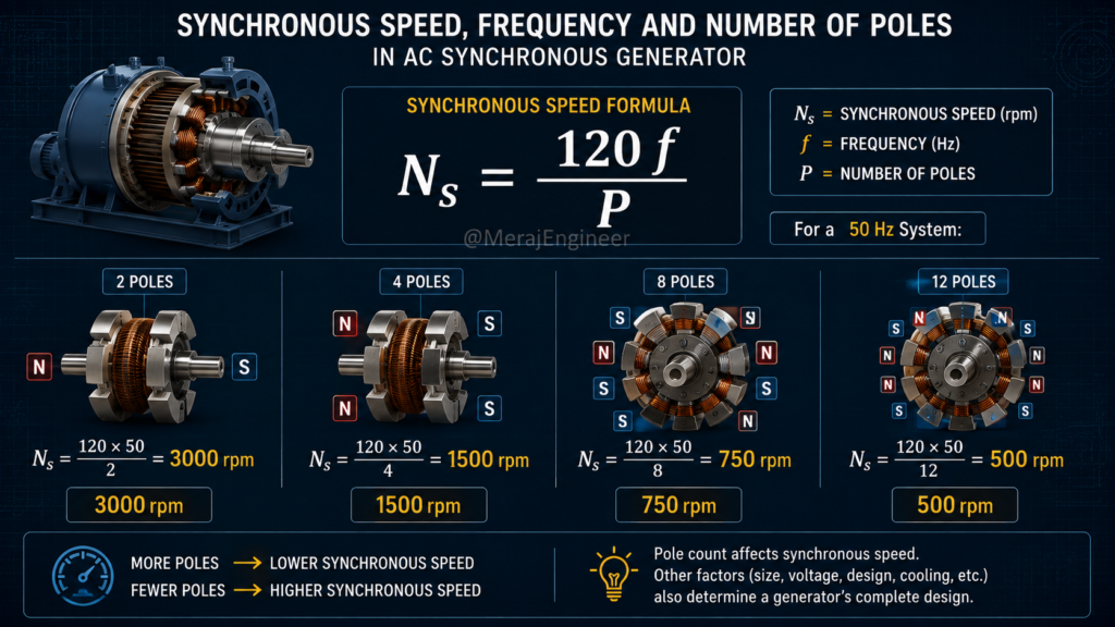
Synchronous generator में Speed (Ns), Frequency (f) और Number of Poles (P) के बीच एक निश्चित गणितीय संबंध होता है।
Ns = (120 × f) / P
आसान याद रखने का नियम (Key Rule):
29 — Industrial Generator और Automotive Alternator
पावर जनरेशन में Industrial Generators और Automotive Alternators दोनों ही अल्टरनेटर सिद्धांत पर कार्य करते हैं, लेकिन इनकी डिज़ाइन और एप्लिकेशन आवश्यकताएँ पूरी तरह से भिन्न होती हैं।
यह एक विस्तृत (Broad) एप्लिकेशन कैटेगरी है, जिसे भारी औद्योगिक लोड और पावर प्लांट आवश्यकताओं के लिए डिज़ाइन किया जाता है।
- विभिन्न प्रकार के Rotor Constructions (Salient/Cylindrical)
- Advanced Excitation Systems (Brushless/Static)
- Dedicated Cooling Systems (Hydrogen/Air/Water)
- Precise Voltage Control & AVR Systems
वाहनों (Vehicles) के लिए विशेष रूप से ऑप्टिमाइज्ड अल्टरनेटर, जो कॉम्पैक्ट आकार में DC पावर सप्लाई प्रदान करता है।
- Rotor Field (Claw-pole design)
- 3-Phase Stator Winding
- Built-in Rectifier Units
- Integrated Voltage Regulator
- Shaft / Pulley & Cooling Fan
Generated 3-Phase AC ➔ Diode Rectifier ➔ DC Power (for Vehicle Battery & Electricals)
30 — Cooling System
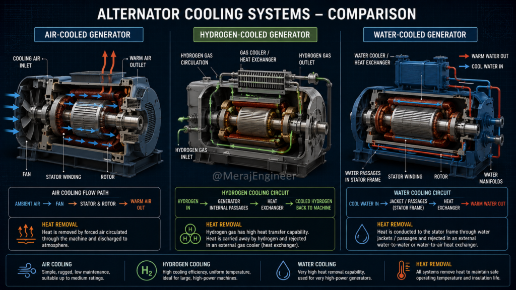
Alternator ऑपरेशन के दौरान विभिन्न प्रकार के एलेक्ट्रिकल और मैकेनिकल Losses के कारण अत्यधिक **Heat (ऊष्मा)** उत्पन्न होती है। यदि इस हीटिंग को नियंत्रित न किया जाए, तो वाइंडिंग इंसुलेशन ख़राब हो सकता है।
हीटिंग उत्पन्न करने वाले मुख्य Losses:
मुख्य कूलिंग पद्धतियाँ (Common Cooling Approaches):
हवा (Air) के फ़ोर्स्ड सरकुलेशन द्वारा हीट रिमूवल। यह स्मॉल और मीडियम साइज अल्टरनेटर्स के लिए सबसे आम और सरल तरीका है।
बड़े पावर-प्लांट जनरेटर्स (Turbo-generators) में कूलिंग मीडियम के रूप में हाइड्रोजन गैस का उपयोग किया जाता है (उच्च थर्मल कंडक्टिविटी के कारण)।
अत्यधिक हाई-पावर और हैवी-ड्यूटी डिज़ाइन्स में स्टेटर वाइंडिंग्स के लिए डायरेक्ट वाटर-कूलिंग सर्किट का उपयोग किया जाता है।
31 — Booster Type, Diode Type और Market Terminology
प्रैक्टिकल फ़ील्ड और मार्केट में अल्टरनेटर के लिए कई तरह के शब्द (terms) सुनने को मिलते हैं। इन सभी को एक ही औपचारिक (formal) इंजीनियरिंग क्लासिफिकेशन का हिस्सा नहीं माना जा सकता, बल्कि यह समझना ज़रूरी है कि कौन-सा शब्द अल्टरनेटर के किस पहलू (Aspect) को दर्शा रहा है।
यह शब्द Voltage Control System को इंडिकेट करता है, जिसमें Automatic Voltage Regulator (AVR) के द्वारा वोल्टेज सेंसिंग और एक्साइटेशन कंट्रोल किया जाता है।
यह Excitation Architecture को दर्शाता है, जिसमें बिना Brushes/Slip Rings के Exciter और Rotating Rectifier से पावर ट्रांसफ़र होता है।
यह कोई यूनिवर्सल क्लासिफिकेशन नहीं है। 1N5408 केवल एक specific semiconductor diode का part number है, न कि Alternator का Type।
यह लोकल मार्केट या स्पेसिफिक मैन्युफैक्चरर टर्म हो सकती है। इसका सही अर्थ जानने के लिए Wiring Diagram और Technical Datasheet देखना ज़रूरी है।
अल्टरनेटर की पहचान करते समय हमेशा पूछें:
“यह Term अल्टरनेटर के किस Aspect — Rotor Construction, Excitation, Control, Cooling या सिर्फ Market Name — को दर्शा रही है?”
32 — Practical तरीके से Alternator की पहचान
यदि आपके सामने कोई अनजान (Unknown) अल्टरनेटर आता है, तो केवल उसकी बाहरी बॉडी या लुक्स देखकर उसका टाइप तय न करें। किसी भी अल्टरनेटर की सटीक पहचान (Identification) के लिए एक व्यवस्थित चरणबद्ध प्रक्रिया (Step-by-Step Sequence) का पालन करना चाहिए।
Nameplate + Drawing + Datasheet = सबसे Reliable Combination
33 — Complete Alternator Construction Journey
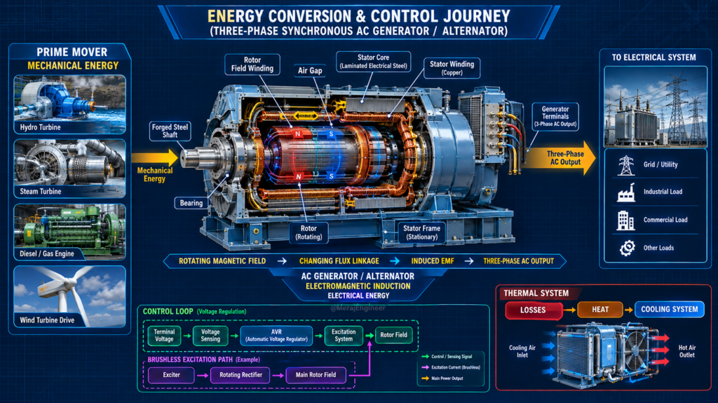
अब तक के सभी घटकों (Components) और प्रणालियों को एक एकल **Engineering Flow Diagram / Journey** में जोड़कर समझते हैं कि प्राइमरी एनर्जी से लेकर इलेक्ट्रिकल आउटपुट और कंट्रोल लूप तक मशीन कैसे कार्य करती है:
↓
Prime Mover
↓
Mechanical Torque
↓
Shaft
↓
Rotor Rotation
↓
Rotating Magnetic Field
↓
Air Gap
↓
Stator Core
↓
Flux Linkage
↓
Stator Conductors
↓
Induced EMF
↓
3-Phase Stator Winding
↓
AC Electrical Output
↓
Voltage Sensing
↓
AVR
↓
Excitation Control
↓
Rotor Field
↓
Heat Generation
↓
Cooling System
↓
Heat Dissipation
📌 हमारा ये लेख भी पढ़ सकते हैं: Winding Data Calculation Formula
34 — Part 2 का Final Recap और Part 3 की Foundation
अब तक हमने Alternator की physical construction, major components, excitation arrangements, rotor constructions और cooling system को एक complete picture के रूप में समझा है।
इस पूरे Part 2 से हमें निम्नलिखित Fundamental Key Concepts स्पष्ट हो जाने चाहिए:
- Stator: यह मशीन का स्थिर (Stationary) भाग होता है।
- Rotor: यह मशीन का घूमने वाला (Rotating) भाग होता है।
- Magnetic Field: मुख्य Magnetic Field को Rotor में इस्टैब्लिश किया जाता है।
- Armature Winding: Stator में सामान्यतः Three-Phase Armature Winding स्थापित होती है।
- Air Gap: Rotor और Stator के बीच एक बेहद कंट्रोल्ड Air Gap रखा जाता है।
- Shaft: Prime Mover से Mechanical Torque लेकर Rotor तक पहुँचाने का काम करता है।
- Bearings: Rotor-Shaft असेंबली को सपोर्ट करते हैं और स्मूथ / कंट्रोल्ड रोटेशन प्रदान करते हैं।
- Excitation System: Rotor Field के लिए आवश्यक DC Excitation उपलब्ध कराने और उसे कंट्रोल करने का काम करता है।
- Brushed Excitation: इस अरेंजमेंट में DC सप्लाई देने के लिए Brushes और Slip Rings का इस्तेमाल होता है।
- Brushless Excitation: इसमें Brushes के स्थान पर Exciter और Rotating Rectifier Assembly का उपयोग किया जाता है।
- Rotating Rectifier Assembly: इसमें लगे Diodes एक्साइटर से प्राप्त AC को Rectified DC में बदलकर Main Rotor Field तक पहुँचाते हैं।
- 1N5408 Specification: यह केवल एक Rectifier Diode का Part Number है; यह किसी Alternator का टाइप नहीं है।
- AVR (Automatic Voltage Regulator): Excitation को रेगुलेट करके जनरेटर के Terminal Voltage को सेट ऑपरेटिंग कंडीशन के अनुसार मेंटेन करता है।
- AVR Clarification: AVR स्वयं इलेक्ट्रिकल एनर्जी जनरेट नहीं करता, केवल कंट्रोल करता है।
- Rotor Types: Salient-Pole और Cylindrical (Non-Salient / Round) Rotor सिन्क्रोनस जनरेटर की प्रमुख रोटर कंस्ट्रक्शन हैं।
- Hydro & Turbo Concepts: यह टर्म्स अक्सर एप्लीकेशन/प्राइम-मूवर और रोटर कंस्ट्रक्शन के संदर्भ में यूज़ होते हैं; इन्हें अकेला क्लासिफिकेशन बेस न मानें।
- Cooling System: जनरेटर का कूलिंग सिस्टम मशीन में लॉसेस के कारण उत्पन्न हीट को बाहर निकालने में मदद करता है।
- Classification Rule: किसी Alternator को केवल एक “Type” से डिफाइन करना पर्याप्त नहीं होता; क्लासिफिकेशन करते समय हमेशा यह बताना ज़रूरी है कि क्लासिफिकेशन किस आधार (Basis) पर किया जा रहा है।
Alternator को एक Line में याद रखें
“Prime mover mechanical energy देता है, shaft rotor को घुमाता है, rotor का magnetic field air gap के माध्यम से stator winding के साथ changing magnetic flux linkage पैदा करता है और इसी के परिणामस्वरूप stator winding में electromagnetic induction द्वारा electrical EMF उत्पन्न होती है।”
यही वह बिंदु है जहाँ Construction (संरचना) की कहानी समाप्त होती है और Electrical Working की कहानी शुरू होती है।
Part 3 में हम निम्नलिखित मूलभूत प्रश्नों के उत्तर देंगे:
- जब Rotor घूमता है, तो Stator winding के साथ magnetic flux linkage वास्तव में कैसे बदलती है?
- Faraday’s Law of Electromagnetic Induction इस प्रक्रिया को कैसे व्याख्यायित करता है?
- Stator winding में Sinusoidal EMF कैसे उत्पन्न होती है?
- Three-Phase Alternator में तीनों Phase EMF के बीच 120° Electrical Phase Displacement क्यों होता है?
- Generated EMF का Equation कहाँ से और कैसे निकल कर आता है?
अब Part 3 में हम इस पूरी chain को Electromagnetic Principle, Mathematics और Practical Generator Operation के साथ विस्तार से समझेंगे।
Conclusion — निष्कर्ष
इस Part 2 में हमने Alternator के physical और constructional aspects को step-by-step गहराई से समझा।
हमने निम्नलिखित सभी महत्वपूर्ण components और systems को उनके engineering context में देखा:
“Alternator केवल Copper और Iron से बनी एक साधारण machine नहीं है।”
सब एक साथ परफेक्ट तालमेल में काम करते हैं।
केवल Construction जान लेना पर्याप्त नहीं है। इसीलिए Part 2 ने हमें अगली सबसे महत्वपूर्ण Stage (Electrical Working Principle) के लिए पूरी तरह तैयार कर दिया है।
Part 3 में हम क्या सीखेंगे?
अगले भाग (Part 3) में हम Alternator की Actual Electrical Working और उसके इलेक्ट्रोमैग्नेटिक सिद्धांतों को विस्तार से समझेंगे।
मुख्य विषय (Key Learning Topics):
- Alternator में Electromagnetic Induction प्रैक्टिकली कैसे कार्य करता है?
- Faraday’s Law जनरेटर पर किस प्रकार लागू होता है?
- Rotor के घूमने से Stator Winding में EMF कैसे Induce होती है?
- Generated EMF स्वभाव से Sinusoidal क्यों होती है?
- Three-Phase EMF कैसे जनरेट की जाती है?
- तीनों Phases के बीच 120° Electrical Displacement क्यों रखा जाता है?
- EMF Equation का डेरिवेशन और फ़ॉर्मूला कहाँ से आता है?
- Frequency, Speed ($N_s$) और Number of Poles ($P$) का आपस में संबंध क्या है?
- Load कनेक्ट करने पर Generator के Voltage और Current का Behavior कैसे बदलता है?
- Excitation बदलने पर Terminal Voltage और Reactive-Power Behavior पर क्या प्रभाव पड़ता है?
- Generator को प्रैक्टिकल Power System Conditions में सुरक्षित रूप से कैसे ऑपरेट किया जाता है?
Part 2 का Final Takeaway:
“Part 2 ने हमें Alternator के अंदर क्या-क्या है और वे components कैसे arranged हैं, यह समझाया। Part 3 हमें बताएगा कि यही components मिलकर electrical energy वास्तव में कैसे generate करते हैं।”
⚠️ Disclaimer (अस्वीकरण)
- Content & Author Responsibility: इस ब्लॉग पोस्ट में दी गई जानकारी केवल शैक्षणिक और सूचनात्मक उद्देश्यों (Educational & Informational Purposes) के लिए है। लेखक (Author) द्वारा जानकारी को सटीक और अपडेटेड रखने का पूरा प्रयास किया गया है, लेकिन इसके पूर्ण सत्य होने, सटीकता या किसी विशिष्ट स्थिति में इसके सीधे अनुप्रयोग की कोई कानूनी जिम्मेदारी या गारंटी लेखक/वेबसाइट की नहीं होगी। किसी भी व्यावहारिक या औद्योगिक कार्य (Practical/Industrial Implementation) के लिए कृपया संबंधित उपकरण निर्माता के मैनुअल और प्रमाणित विशेषज्ञ की सलाह लें।
- AI Assistance & Images: इस लेख की सामग्री के संपादन, शोध और इसमें उपयोग की गई कुछ विजुअल इमेजेस (Diagrams/Illustrations) को बेहतर प्रस्तुति के लिए AI (Artificial Intelligence) टूल्स की सहायता से तैयार/जेनरेट किया गया है। ये चित्र केवल अवधारणाओं (Concepts) को समझाने के लिए सांकेतिक रूप से उपयोग किए गए हैं।
🔗 AC Generator Series Navigation
AC Generator: कैसे बनती है AC Electricity? Alternator की पूरी कहानी
AC Alternator की Construction: Stator, Rotor, Winding और Excitation की पूरी कहानी
Alternator Electrical Working, EMF Equation & Operation
Faraday’s Law, 3-Phase 120° displacement, Voltage behavior और Power system operation की पूरी जानकारी।