
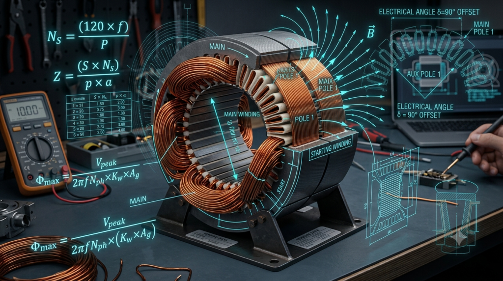
Single Phase Induction Motor (Capacitor Run / Two-Value Capacitor) ka winding data local hit-and-trial methods se nikalna risk bhara hota hai. Crompton, Havells, aur Kirloskar jaisi leading electrical OEMs me motor design Electrical Machine Design (EMD) ke rigorous scientific formulas par based hota hai.
Is master technical guide me hum core slot geometry, magnetic flux loading, conductor current density, aur slot fill factor ko include karke 1 HP Single Phase 4-Pole Induction Motor (24 Slot) ka accurate winding data step-by-step calculate karenge.
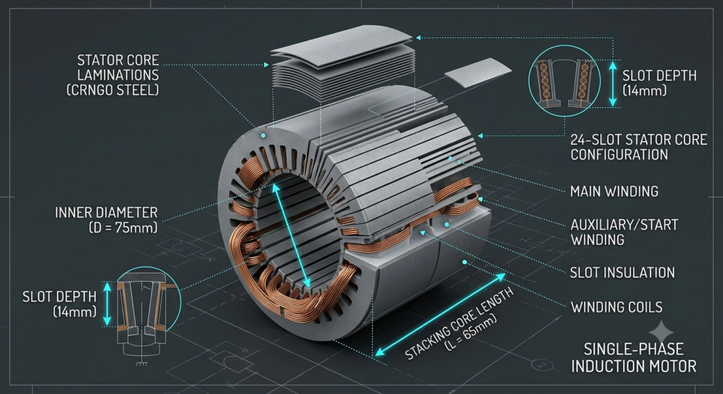
Sabse pehle Stator Core ki exact physical dimensioning aur electrical parameters note kiye jaate hain.
- Nominal Output Power (P): 1 HP = 746 Watts
- Operating Voltage (V): 230 V AC, 50 Hz
- Number of Poles (P): 4 Pole
- Synchronous Speed (Ns): (120 × f) / P = (120 × 50) / 4 = 1500 RPM
- Number of Stator Slots (S): 24 Slots
- Stator Inner Diameter (D): 75 mm = 0.075 m
- Gross Stator Core Length (L): 65 mm = 0.065 m
- Target Efficiency (η): 75% ya 0.75 (Class F Insulation, High-Efficiency Industrial Standard)
- Power Factor (cos φ): 0.80 lagging
- Average Magnetic Flux Density (Bav): 0.45 Wb/m² (CRNGO Silicon Lamination Standard)
Industrial design standards ke mutabiq split-phase/capacitor motors me running load continuous carry karne ke liye current distribution fix hota hai:
-
Main Winding (Run Winding) Current (Im): Total Full Load Current ka 80% carry karti hai.
Im = 0.80 × IFL = 0.80 × 5.40 A = 4.32 Amperes
-
Auxiliary Winding (Start Winding) Current (Ia): Starting torque aur continuous phase displacement ke liye approx 50% load duty share karti hai.
Ia = 0.50 × IFL = 0.50 × 5.40 A = 2.70 Amperes
Back EMF (Em) core resistance loss adjust karne ke baad supply voltage ka approx 95% hota hai (Em ≈ 0.95 × 230 V = 218.5 V):
Quadrature phase angle (90° electrical displacement) aur high starting torque build-up ke liye Auxiliary Winding me Main Winding se 1.30 × (130%) turns hote hain:
Target Current Density J = 5.0 A/mm²:
Required Conductor Diameter (dm):
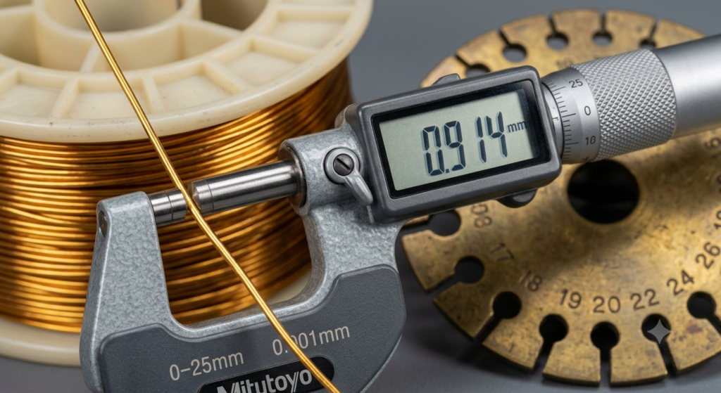
- Industrial Selection: 20 SWG Dual-Coated Super Enamelled Copper Wire (Bare Conductor Diameter = 0.914 mm, Bare Area = 0.656 mm²). Multi-strand optimization me isko 23 SWG Dual Parallel se bhi rewinding ki ja sakti hai.
Target Current Density J = 5.5 A/mm²:
Required Conductor Diameter (da):
- Industrial Selection: 22 SWG Super Enamelled Copper Wire (Bare Conductor Diameter = 0.711 mm, Bare Area = 0.397 mm²).
- Total Gross Slot Area (Aslot): 85 mm²
- Slot Insulation Area (0.25mm Nomex/Garware Paper + Wedge): 20 mm²
- Net Available Slot Copper Space: 65 mm²
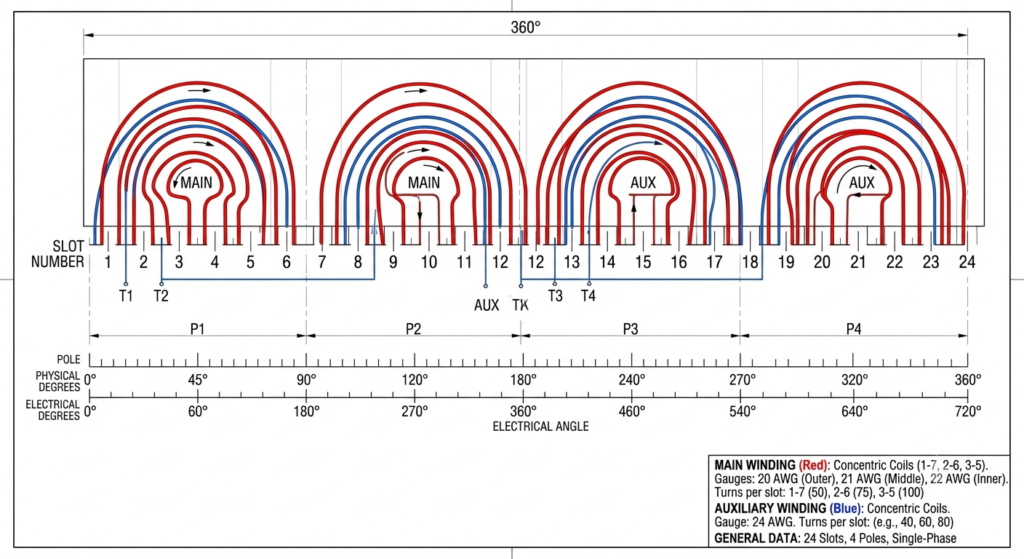
Standard Concentric 24-slot arrangement me har slot me Main aur Auxiliary donor coils mix hoti hain:
- Conductors of Main Winding per Slot: 150 / 3 = 50 Conductors
- Conductors of Auxiliary Winding per Slot: 194 / 3 = 65 Conductors
(Enamelled wire outer diameter packing factor consider karne ke baad ye 42% net slot space factor deta hai, jo perfect factory fit hai).
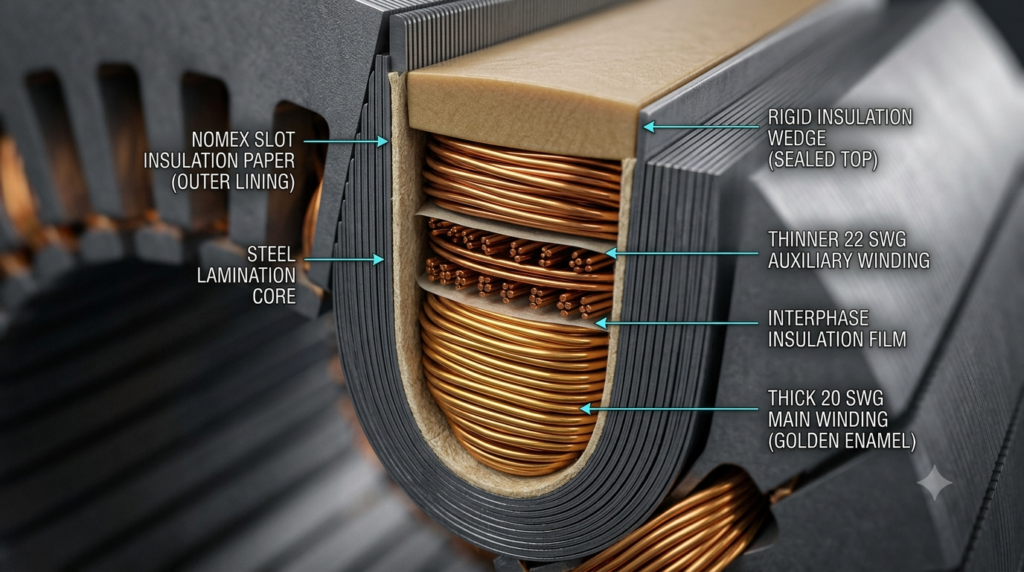
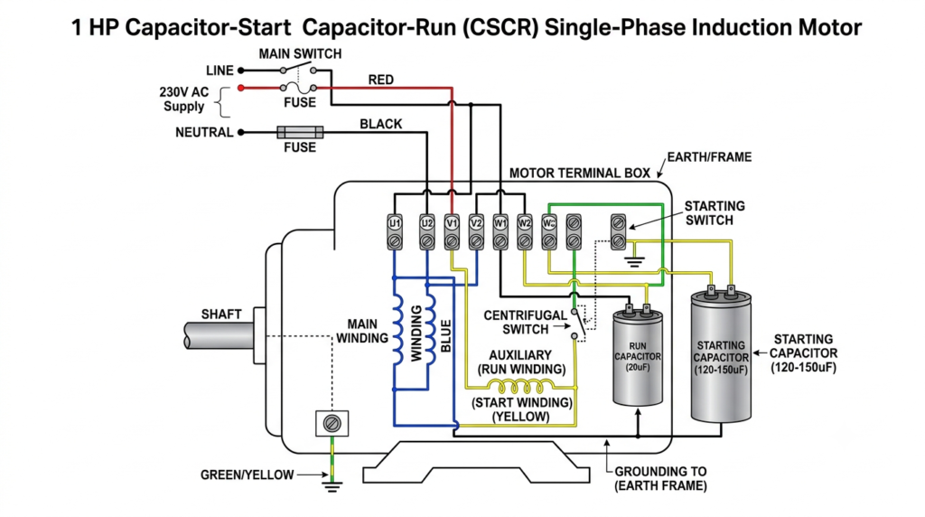
Niche di gayi table Crompton / Havells industrial standards ke anusar finalized motor winding sheet hai:
| Parameter | Main Winding (Run Coils) | Auxiliary Winding (Start Coils) |
|---|---|---|
| Coil Pitch Arrangement | 1-3, 1-5, 1-7 (Concentric) | 1-4, 1-6, 1-8 (Concentric) |
| Total Turns Per Pole | 150 Turns | 194 Turns |
| Turn Distribution (Per Pitch) | 1-3: 35 T | 1-5: 55 T | 1-7: 60 T | 1-4: 44 T | 1-6: 70 T | 1-8: 80 T |
| Wire Gauge (SWG) | 20 SWG Super Enamelled | 22 SWG Super Enamelled |
| Bare Wire Diameter | 0.914 mm | 0.711 mm |
| Capacitor Rating | 20 µF / 440V AC (Run Cap) | 120-150 µF / 275V AC (Start Cap) |
| Connection Configuration | 4-Pole Series / Parallel | 4-Pole Series Connection |
Is guide me shamil sabhi motor winding calculations, flux density formulas, aur wire gauge selection parameters standard Electrical Machine Design (EMD) principles aur IEEE Industrial Standards ke anusar tay kiye gaye hain. Rotating machinery ke foundational concepts ke liye aap hamara AC Generator & Alternator Working Guide refer kar sakte hain. Data ki accuracy ka pura dhyan rakha gaya hai, fir bhi practical implementation se pehle certified electrical engineer ki salah zaroori hai.
Is article me istemaal kiye gaye technical diagrams aur illustrations educational reference ke liye AI Image Prompts se generate kiye gaye hain. Real-world stator layout aur wire colors me variation ho sakta hai.
Is technical data ke use se hone wale kisi bhi equipment damage, technical failure, ya loss ke liye ye website aur iska author zimmedar nahi honge.